pcb

Joystick Mouse by Sebastian Morales

If you are reading this post it is likely that you spend more than 4 hours a day in front of a computer. Depending on what you are doing this can create a lot of strain on your wrists, arms and shoulders. 

I remember a friend of mine would have a collection of mice on her desk, every couple of hours she would grab a different one, no matter how ergonomic the mice was she would eventually get tired of the position.  

I think this is because all of these mice are meant to be used in only one configuration, and no matter how ergonomic it is, the human body is meant to move. 

Inspired by this challenge, I wanted to create a mouse that didn't locked the user into a single position, one that could be used upside down, laying down or standing up far away form the computer.  

Welcome the Arduino Joystick Mouse!

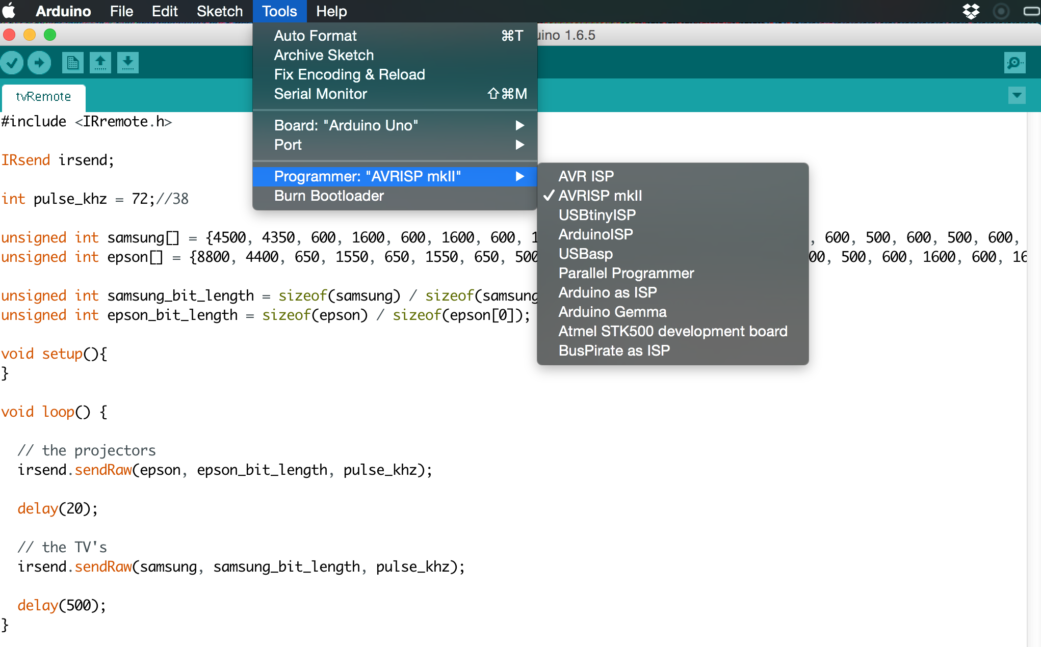
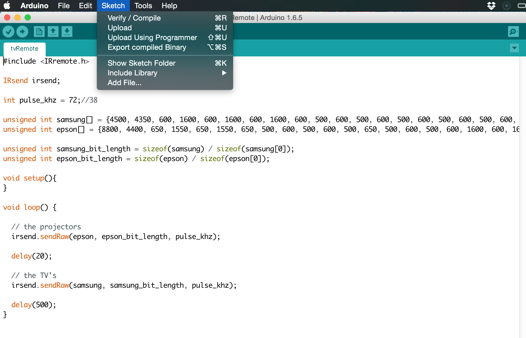
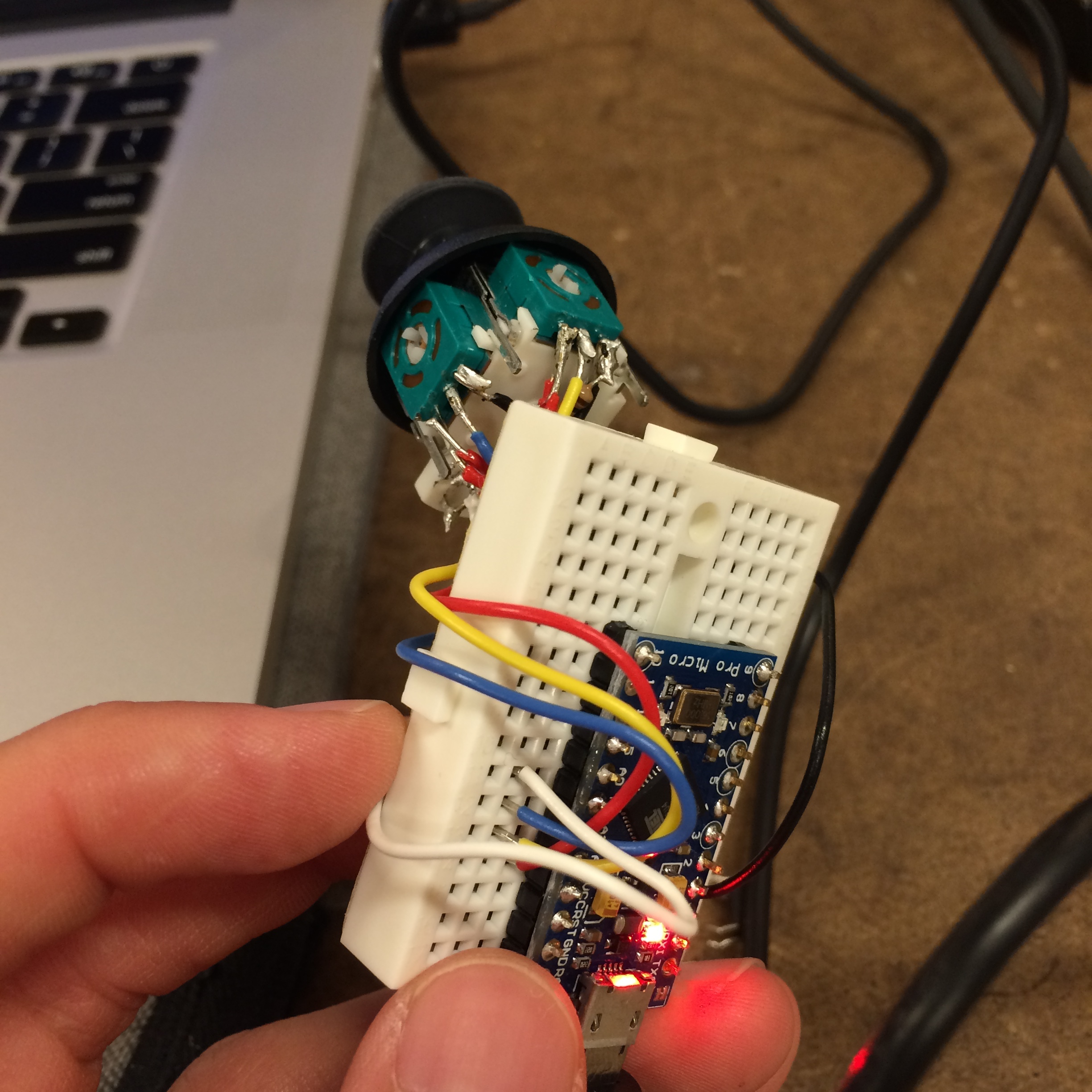
Turns out that the Arduino Leonardo is perfect for this since it can out of the box access your mouse controls through USB. 

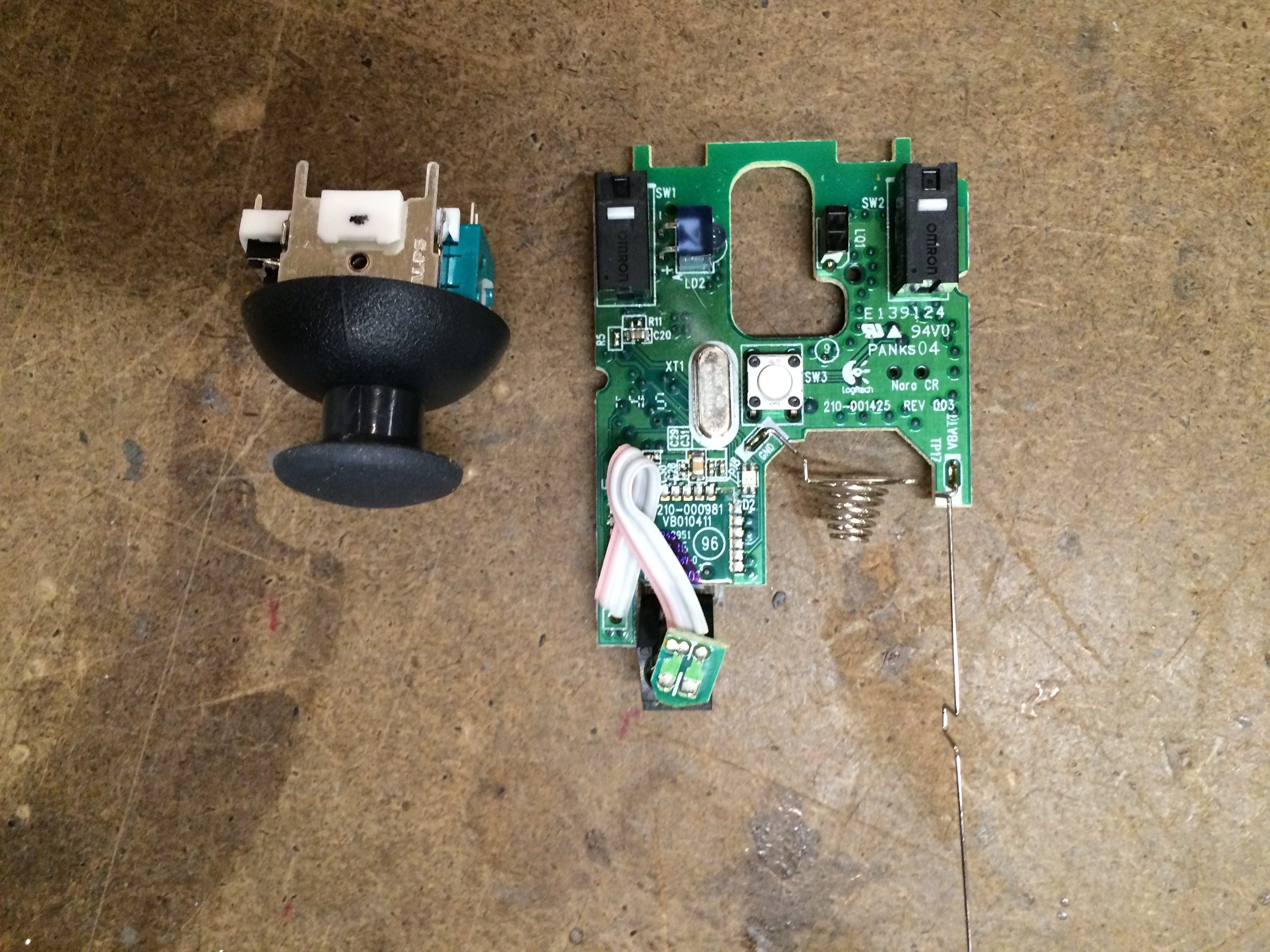
The prototype is quite simple, it has a 2DOF joystick plus a push button. I also added two more buttons as a regular mouse would. An additional idea was to include a 9DOF sensor to detect complex movements. 

This could transform the mouse into a 3D mouse, ideal for creating complex CAD models where you can easily move around your models with elegant precision. This however, requires additional programming that I didn't prioritize in these short weeks. 

An additional advantage of using such 9DOF sensor would be programming movement patterns, perhaps you could copy and paste by simulating the motion of spooning and pouring for example. 

A lot more complex behaviors could be programmed as desired, this means that the firmware inside the mouse should be able to update easily, this means that the brains inside of the mouse should be able to update simply thought the same cable. This made the ATMEGA32U4 the ideal candidate.

After simplifying my MVP for my first prototype I settled on having a simple mouse that could click (right and left), scroll  and move the cursor. Pretty basic but simple to modify if I ever decided to add the 9DOF sensor. 

Eagle 

Ripup, route, ratsnest... your 3 favorite commands while laying out the circuit 

Once I finally simplified my traces and thought it could work it was actually time to make it. 

I skipped a couple of pictures here but it involved printing on vinyl and transferring the ink by pressing it and heating it inside a hair iron. 

Then dropping it on acid.

The process didn't came out without its own problems. 

...like all my pads touching or even completely connected.

The solder is the right place but it looks lime the solder is a little too liquid.

Time to do a continuity check!

MUSIC EVERYTHING BEEPS!!!

So back to the microscope and try to make  things stop touching. Hard to see it but there is a knife trying to separate two paths that looks like might be touching. 

...test again... beeps again... f this...

Final thoughts

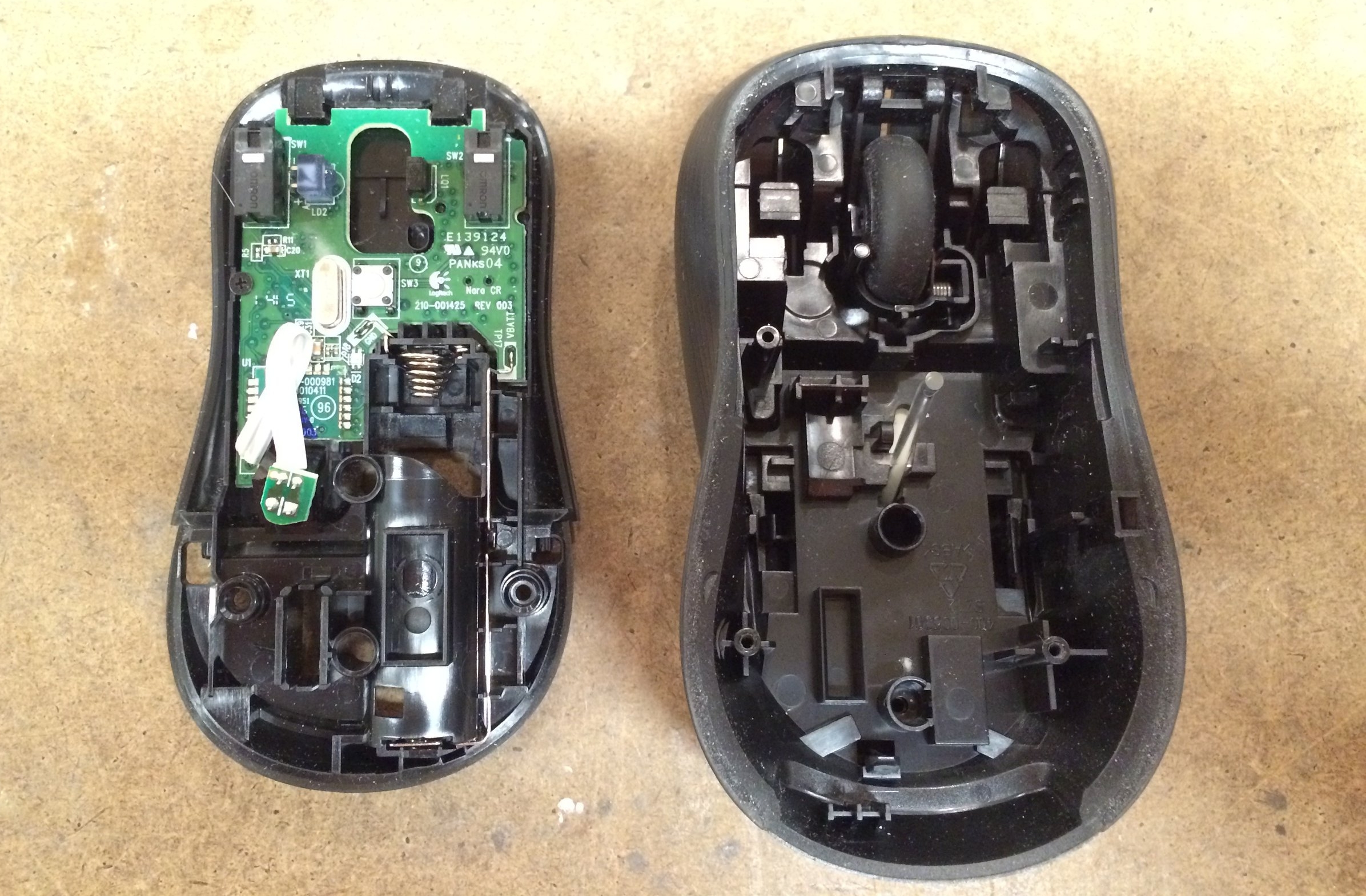
My final (not working) prototype is about (pretty much exactly) the same size as my original one. Making me reconsider if this was the right project to try this on. 

Populating the Board by Sebastian Morales

Creating the solder stencil

Once the board has been printed, milled or etched. Once the board is ready to be populated, there are a couple of steps that one needs to do first. 

In order to facilitate the process, it is best to apply a uniform layer of solder paste in all the pads where components will be solder. To do this a good practice is to laser etch a sheet of acetate to make the mask.

The settings might vary depending the film used as well as the laser selected. The recommended settings where 10 power 10 speed and seemed to be working fine for my first tests. 

Applying the solder mask

seconds prior to applying the solder paste

seconds prior to applying the solder paste

Before you even start this make sure all your components are out, once you apply the paste you don't have much time so you don't want to waist it looking for that 1uF capacitor.

It is best if the board is constrained while the solder is applied, that way you don't risk the stencil to move and the solder will be applied on the pads.

After locking the board and positioning the stencil, apply some solder paste at the top or bottom of the stencil. In one uniform (maybe two, max 3) movement apply the paste by gliding a plastic spatula (credit card) over the board.

Carefully remove the stencil, carefully to not smudge the solder paste on the pads.  


If everything went according to plan you should have something that looks like this!

Placing components

Perhaps one of my favorite steps in the process. If you followed the instructions you already have everything you need out. Using the manual pick and place make sure to delicately place the components in the right location and orientation. Don't worry if they are slightly crooked, they will magically aligned once the solder flows. 

Melting the solder

Here a picture of the settings used in case they are useful. 

I guess the only other thing to mention is to allow for the machines to heat up before using them.


I think it is ideal practice to heat all the board a little before focusing on one specific area. Move the heat gun around the entire board, soon you will see the solder change color, transforming from a matte gray to a very shiny silver. You will also see how the solder groups together.

Test before you power

To my naked eye, the board looks great, there seems to be some two resistors bridging (top left). This is not really a problem since they are where already connected in parallel in the schematics. 

Perform some basic continuity tests to make sure only what is supposed to be connected is connected. This can save you some severe damage to your computer (in case you would connect this to your computer).

Programming the board

So you did everything right?

Congratulations, you are almost there. The class website has some great resources, as well as links to more resources. Go there and learn how to properly use the burn the boot loader to later be able to upload arduino sketches. 

Programming the board by Sebastian Morales

The foot pedal was being used so I ended up using the fancy pick and place machine. 

Heated the board a little...

BEAUTIFUL! Actually two of my resistors are connected together but after looking at the diagram you know that this are connected regardless. In other words, no need to worry. 

I skipped a couple of steps here, well, not really but I didn't include them in the documentation. 

It is IMPORTANT to verify that all the components are solder correctly before connecting them to a computer, to power for that matter. 

To test this grab a multimeter and verify that the grounds are connected to the grounds and nothing else. The same goes for the powers. 

Even after doing this, I was still a little nervous so I actually used a power supply instead of my computer (to power it). It turned out that all the components were solder correctly but better to be safe. 


Programing / Burning the bootloader

In this case I was using the AVRISP MKII to burn the bootloader and then to upload my sketch to the atmega. 

There are a couple of tutorials on how to do so online but I found them a little confusing. The actual process is really simple. 

First make sure the pogo pins are oriented in the right direction. The green LED should light up on the programer. 

  • Select the right Programer from the "Tools" menu. 
  • Click Burnbootloader
  • Upload sketch using programer (⇧⌘U)

Note: I had to change the frequency variable on the code (pulse_khz) from 36 to 72. I think I had the wrong crystal so my code was running twice as fast. After some frustrating attempts I was able to turn the projector in the classroom off.

Arduino Mouse by Sebastian Morales

A couple of months ago, while still working as a full time engineer I would have my desk filled with mice; a regular mouse, a 3D mouse, a fancy mouse, a tiny mouse, a wireless mouse... you get the idea... Although I did have one that was my favorite, I would eventually get tired of the position and switch to another one. This made me think about creating a mouse that allowed you to change positions, a mouse that would work even if you where standing upside down.